CV Mutant Manual
The concept behind CV Mutant
CV Mutant is designed in the first place as a translation matrix for CV Signals. The envelope you can create with CV Mutant is mapped from the left to the right to the full range of a CV signal. A common way to describe a CV signal in Reason is from 0 to 127. A CV signal with a value of 0 will map to the left side of the envelope, and a value of 127 to the right side. All other values map to one of the stages of the envelope, depending on the selected number of stages and the Widths set up in each stage.
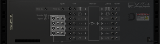
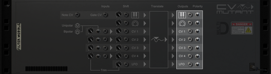
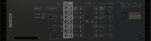
Inputs/Outputs
There are 4 different types of inputs. The CV Inputs, Big knob, LFO and Trigger. The latter 3 are basically just CV generators that are internally routed to be translated by the envelope.
Each of the inputs is parallel processed. So you don't have to choose which one to use, you can use them all at the same time.
Big Knob
The most simple and direct form of input. Turn the Big Knob to move the position in the envelope from the beginning through to the end.
Tip: Create several CV Mutants and control them all with a single combinator rotary. Let each CV Mutant control a different parameter and give them each a different envelope. This allows you to do extremely complex transitions, with several parameter perfectly attuned to each other, with just a single twist of a knob!
CV Inputs
There are 4 CV Inputs on the back. By default the inputs expect a unipolar signal (from 0 to 127). If your signal is Bipolar (-64 to +64), you can flip the polarity switch next to the CV Input and CV Mutant will internally convert it to a unipolar signal before passing the value on to the envelope. Trim knobs are also available to lower the input before CV Mutant processes it to the envelope.
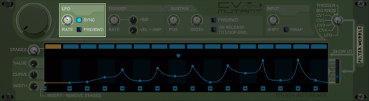
LFO
The LFO is like most other LFO's in Reason. It can have a free rate, or it can be synced to tempo. The range of the rate is from 0.010Hz to 100Hz in free mode, or from 1/32 to 32/1 in synced mode.
The LFO produces a value from 0 to 127 in the shape of a ramp (0 to 127, repeat) or a triangle (0 to 127, back to 0, repeat) that matches the LFO rate. The generated value is then passed to the envelope.
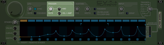
Trigger
The trigger channel is triggered by either Midi input, the combinator's 'Receive Notes' option in the programmer, or by the NOTE and GATE CV inputs on the back. Once triggered, CV Mutant plays the envelope once.
The play rate is set by the RATE knob, and can be scaled by the pitch of the note using the KBD knob. The KBD knobs accepts positive and negative values. At 0, no rate scaling is applied. The higher (or lower when negative) the value, the more extreme the scaling will be. Positive values will make a high pitched note faster and a low pitched note slower. A negative KBD will invert this effect.
The output of the trigger channel can be scaled by the velocity of the note using the VEL > AMP knob. A value of zero will not apply amplitude scaling and play the envelope 'as is'. When the VEL > AMP knobs is turned all the way to the right, the output is fully scaled by the velocity. So if the note barely has velocity, the amplitude will remain practically zero.
Trigger sustain
Also part of trigger, is the sustain loop. As long as a note is held or the gate is opened, the trigger will play normally until the end of the sustain loop is reached. From there it'll start looping. There are 4 loop modes:
FWD: Set by a positive WIDTH, play position is reset to start of the loop when the end is reached.
BWD: Set by a negative WIDTH, play direction is reversed. When the start of the loop is reached, the play position is reset to the end of the loop.
FWD/BWD: Either positive of negative WIDTH and FWD/BWD is switched on, play direction is reversed at either end.
Fixed position: WIDTH of zero, play position will remain at the sustain loop's position.
When the note is released, the play direction is set to forward again. Optionally the play position can be enforced the end of the loop position when the note is released, which guarantees a fixed position upon note release. Otherwise the note will continue from the position is was when the note was still on.
The primary position of the loop can be set with the POS knob. The range of the POS knob matches the entire width of the envelope. The secondary position is set by the WIDTH knob. A positive WIDTH will move the loop end to the right, while a negative width will move the loop start to the left. The loop start and end positions can be seen in the display.
CV Outputs
Each of the inputs also has an output. The output is unipolar by default, but can be converted to bipolar by flipping the switches.
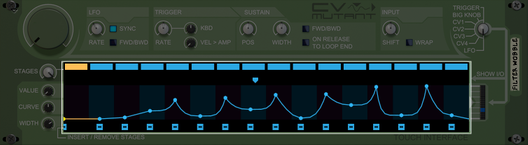
Envelope
The envelope consists of a maximum of 16 stages. Each stage is represented on the display by the rectangles at the top and the small circles on the curve itself.
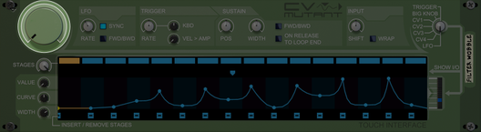
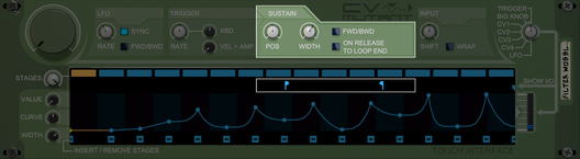
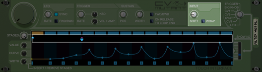
Interactive display
The easiest way to set up the envelope is using the interactive display. The display consists of 4 sections:
The topmost is the stage selection. Here you can select any stage, which is then marked yellow. The selected stage can be edited by the separate knob (see below). The stages that are currently in use by the envelope are colored a brighter blue.
Directly below the stage selection is some reserved space which shows the input of the selected channel. If you're monitoring the trigger channel, the sustain loop position is also shown here.
The largest section is where you can see the actual envelope. The envelope area has 16 columns as background for visual support. Each stage is represented by a small circle that can be moved by clicking and dragging it. You can also click and drag the line between the circles to adjust the curves between the stages.
The bottom portion of the display is used to add or remove stages. Click one of the [-] marks to remove the stage directly above it. Click anywhere in the black to add a stage on that position.
Stage properties
A stage consist of a value, a curve that determines the progression towards the next stage, and a width, that defines the width of the stage relative to the other stages. Based on these the whole envelope is calculated. Normally using the display's drag and drop function will take care of these properties, but you can access them directly using the knobs on the left of the display. These knobs control the currently selected stage, which is marked with a yellow color on the display. Select a stage by clicking anywhere on the envelope, or using the rectangles on the top. Using the rectangles, you can also select stages that are currently not in use by the envelope.
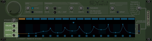
Value
Each stage has a value associated with it. The value of the stage is used as output for the envelope, if the input is mapped to that stage. If the input is mapped between stages, the output will be interpolated between the values of the stages.
Curve
The curve defines how the interpolation between 2 stages takes place. It can be linear, ramped in various degrees or near instant. The center position of the curve knob indicates a straight and smooth interpolation between the 2 stages. Turning the knob to the left will cause a logrithmic interpolation, and turning it to the right will cause an exponential interpolation. The extreme left and extreme right values are practically instant at the left or right side of the stage.
Width
Increasing or decreasing the width will change how much 'mapping space' that stage possesses. This can make the transition between 2 stages significantly faster or slower in relation to other stages.
Note: The total width is always the same. It always has a range from 0 to 127. By decreasing the width of a stage, you automatically increase the width of others.
Input pre-processing
Before the input is send the the envelope for translation, it is pre-processed. During this stage the input is altered a bit to tweak the result you wish to achieve. The steps are:
Trim, a common feature in a lot devices. It allows you to reduce the magnitude of the input.
Polarity, converts bipolar to unipolar if switched on.
Shift, simply add's to or subtracts from the input. This can cause values below 0, or above 127.
Wrap, values below 0 or above 127 are normally clamped. But when wrap is enabled, these values continue on the other side of the envelope.
Shift can be applied in 2 ways. The Shift knob on the front applies shift to all inputs simultaniously. You can also attach a CV cable to the back for individual channels. The global shift and the channel specific shift can be applied at the same time, and are added to each other. How much shift is applied, can be seen by a magenta displacement arrow.
Note: Wrapping is a feature that was already implemented for LFO in FWD mode in version 1 of CV Mutant. In version 2 it has been made available as option for all inputs. Because of backwards compatibility, wrapping is always enabled for LFO-FWD and can not be switched off.
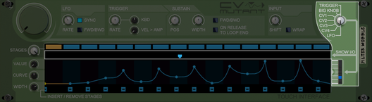
Input/Output monitoring
All channels are separately processed and can be used simultatiously. However, you can only show a single channel at a time on the I/O. The I/O consists of the area directly above the envelope, which shows the channels' current input position. This position is the actual position being used to read the envelope. Any pre-processing has already taken place to this input value, like Shift, Wrap and Trim.
The output value is display on the LEDs directly to the right of the envelope.
Copyright © 2013 - All Rights Reserved