CV Mutant Manual
The concept behind CV Mutant
CV Mutant is designed in the first place as a translation matrix for CV Signals. The envelope you can create with CV Mutant is mapped from the left to the right to the full range of a CV signal. A common way to describe a CV signal in Reason is from 0 to 127. A CV signal with a value of 0 will map to the left side of the envelope, and a value of 127 to the right side. All other values map to one of the stages of the envelope, depending on the selected number of stages and the Widths set up in each stage.
Inputs/Outputs
There are 3 different types of inputs. The Big knob, CV Inputs and the LFO. Each of the inputs is parallel processed. So you don't have to choose which one to use, you can use them all at the same time.
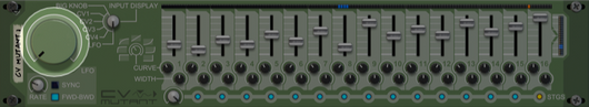
Big Knob
The most simple and direct form of input. Turn the Big Knob to move the position in the envelope from the beginnen through to the end.
Tip: Create several CV Mutants and control them all with a single combinator rotary. Let each CV Mutant control a different parameter and give them each a different envelope. This allows you to do extremely complex transitions, with several parameter perfectly attuned to each other, with just a single twist of a knob!
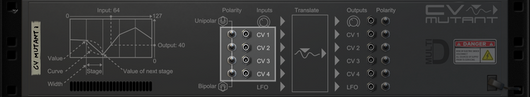
CV Inputs
There are 4 CV Inputs on the back. By default the inputs expect a unipolar signal (from 0 to 127). If your signal is Bipolar (-64 to +64), you can flip the polarity switch next to the CV Input and CV Mutant will internally convert it to a unipolar signal before passing the value on to the envelope.
LFO
The LFO is like most other LFO's in Reason. It can have a free rate, or it can be synced to tempo. The range of the rate is from 0.010Hz to 100Hz in free mode, or from 1/32 to 32/1 in synced mode.
The LFO produces a value from 0 to 127 in the shape of a ramp (0 to 127, repeat) or a triangle (0 to 127, back to 0, repeat) that matches the LFO rate. The generated value is then passed to the envelope.
CV Outputs
Each of the inputs also has an output. 1 for the Big Knob, 4 for the 4 CV Inputs and 1 for the LFO. The output is unipolar by default, but can be converted to bipolar by flipping the switches.
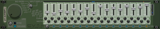
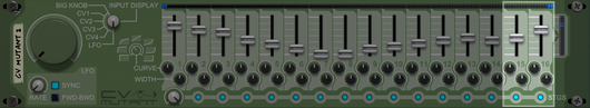
Envelope
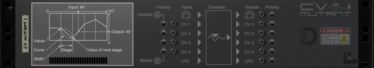
The envelope consists of 16 stages. Each stage represented by a slider for it's value, a curve that determines the progression towards the next stage, and a width, that defines the width of the stage relative to the other stages.
Value
Each stage has a value associated with it. The value of the stage is used as output for the envelope, if the input is mapped to that stage. If the input is mapped between stages, the output will be interpolated between the values of the stages.
Curve
The curve defines how the interpolation between 2 stages takes place. It can be linear, ramped in various degrees or instant. The center position of the curve knob indicates a straight and smooth interpolation between the 2 stages. Turning the knob to the left will cause a logrithmic interpolation, and turning it to the right will cause an exponential interpolation. The extreme left and extreme right values are practically instant at the left or right side of the stage.
Note: There is a graphic on the front panel illustrating this behaviour.
Width
Increasing or decreasing the width will change how much 'mapping space' that stage possesses. This can make the transition between 2 stages significantly faster or slower in relation to other stages.
Note: The total width is always the same. It always has a range from 0 to 127. By decreasing the width of a stage, you automatically increase the width of others.
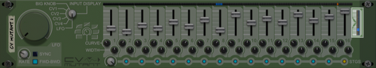
Stages
CV Mutant does not always have to use all 16 stages. By default, only the first 2 required stages are enabled. You can increase how many stages are enabled with the Stage Count knob below the envelope.
Note: The total width is always the same. It always has a range from 0 to 127. Increasing or decreasing how many of the stages are enabled does not make the envelope longer or shorter. It simply increases or decreases the detail.
Example on the back
A graphic illustrating the relation between different stages can be found on the back of CV Mutant.
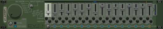
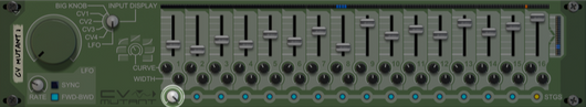
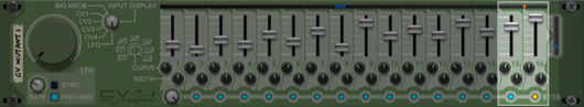
Indicators
Since curve displays are currently unavailable for Rack Extensions it can be tricky to see what is happening under the hood. This is especially evident when changing the width of the various stages. The LED display along the top of the stage controls indicates which stage the input is currently at taking width into account. The LED meter on the right indicates the current output CV value based on the Input Display knob selection.
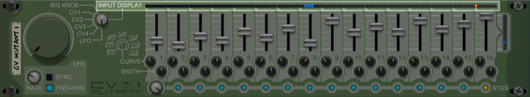
Input Display selection
You can choose which of the channels you wish to monitor with the Input Display knob.
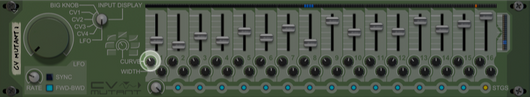
Input Meter
The LED meter above the envelope shows the current input and how it's used as an index for the envelope by using blue leds. Varying widths and amount of stages are taken into account when displaying the meter. The pointy end at the top of a stage, points to the spot on the LED meter where the stage's value is not interpolated from the previous stage or into the next stage.
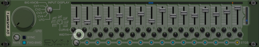
The red LED on the Input Meter
The red LED indicates the position on the Input Meter where the envelope ends.
The last stage of the envelope defines the value at the very end of the envelope. Because each stage's Curve and Width define the shape into the next stage, the Curve and Width for the last stage have no purpose. The partially working last stage can be recognized by the light, that indicates if the stage is enabled, shining red instead of blue. Another indication is the the red LED on the Input Meter, which is positioned at the beginning of the last stage.
The exception to this, is the forward playing LFO. The forward playing LFO is designed to provide a smooth transition from the last stage back to the first. When forward playing LFO is enabled, the Curve and Width of the last stage are used to define how the LFO returns to the value of the first stage. This behaviour can be recognized by the color of the last stage's light shining blue instead of red. Also, the red LED on the Input Meter is now positioned at the end of the last stage instead of the beginning. A final indication that the envelope is now smoothly repeating itself, is the blue LEDs indicating the Input's index, is positioned partially at the end and partially at the beginning of the envelope, when the index is transitioning from the last stage back into the first.
Output Meter
The result of the currently displaying input, being translated by the envelope, can be monitored in the Output Meter.
Copyright © 2013 - All Rights Reserved